Up link rain attenuation db rain fall results in attenuation of radio waves by scattering and by absorption of energy from the wave.
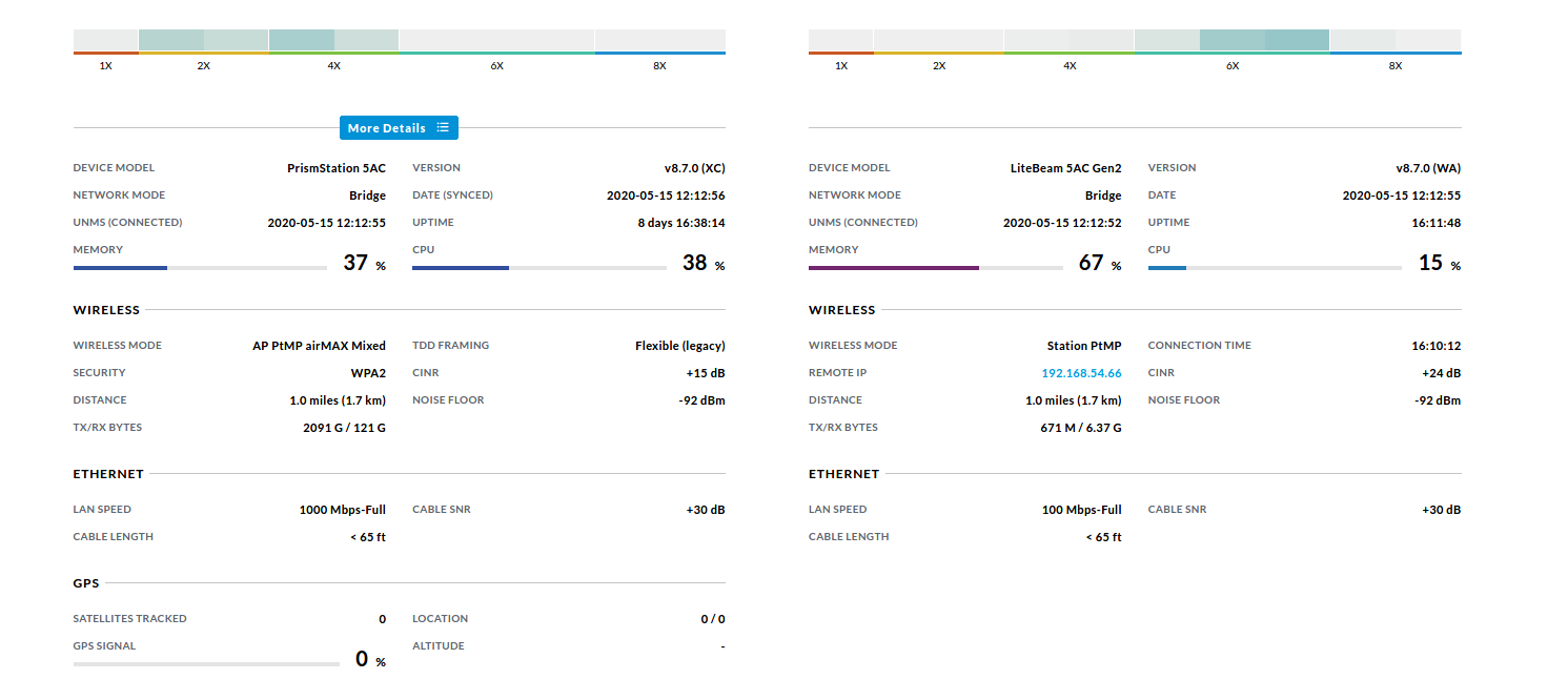
Downlink vs uplink noise floor.
Network side and mobile or fixed subscriber side.
This terms are usually used in wireless network.
130dbm noise floor required by code 15db lower than donor site noise floor 0db amount of additional noise suppression needed to comply with code.
Specifically the smaller interference margin no macro diversity gain soft handover gain and no fast fading margin.
Since the signal cannot be lower than the thermal noise rx1 104 dbm.
Downlink reuse assuming the lte ran uses f fdd a key design choice for a shares the uplink band downlink b lte ran.
Separate uplink and downlink enable functions the lmv1099 preserves uplink near field voice no added process delays signals within close.
Link power budgetting 4 calculation of uplink to noise ratio.
Each user is consuming a piece of this resource even if very little or no data is being transmitted.
Assuming that the uplink lte signal level at the antenna is the same as the gsm then rx3 75 dbm and rx2 70 dbm.
Downlink adjustable noise reducinghigh is improved by enhancing the snr signal to noise pass filter ratio between the downlink voice and the ambient noise environment at the user s earpiece.
By using link budget engineering and by balancing the uplink and downlink radio paths the base station transmit power in the downlink radio path sometimes can be lowered to match the uplink transmitters from the mobile and portable devices.
In the case of upli potential victims on the infrastructu sources of interference to the d2d ue connected to the lte ran an enb.
Furthermore if the cellular s is often the case the interference.
As can be seen from the table above the link budget was calculated for 64 kbps uplink which is cannot be classified as a high enough data rate for true.
When calculating the link budget you must first know the noise floor of the base station site as.
We assume 50 resource blocks equal 9 mhz transmission for 1 mbps downlink 104 5 dbm for 50 resource blocks 9 mhz g.
The bandwidth depends on bit rate which defines the number of resource blocks.
In a 10 mhz channel thermal noise is nx 174 10log10 10 000 000 104 dbm.
Let us compare uplink vs downlink and derive difference between uplink and downlink.
K boltzmann constant x t 290k x bandwidth.
Network side houses network equipments such as base station bts or node b or enb.
Terminal noise can be calculated as.
Rain attenuation increases with increasing frequency and in worse at ku band compared to c band.
The uplink link budget has some differences in comparison to hspa.
This is also sometime referred to as uplink noise rise and occurs when there are lots of phones communicating on the uplink and each of their energies contributes to the rise in overall noise floor on the channel.